Home » Wind Turbine » Overvoltage Protection for Wind Turbines
Overvoltage Protection for Wind Turbines
Due to their principle of operation, wind turbines have to be set up outdoors and are used in a wide range of climatic environments. Wind power plants, being installed outdoor, may be subject to direct and indirect overvoltages of atmospheric origin, besides being subject to switching overvoltages. Lightning protection allows risks for people (mainly the personnel in charge) and maintenance operations due to damages on structure and on the internal components to be reduced and measures against economical losses because of drop of energy production due to the plant failure to be taken.

If the wind turbine is installed on a building and significantly modifies the outline of the same, a new assessment of the lightning risk is necessary to verify whether installation of an LPS (Lightning Protection System) or modification of that already present are needed. If the wind turbine is installed on the ground, stand-alone or in a wind power plant, due to its height and being often the highest structure in the surrounding area, it represents an “ideal target” for atmospheric discharges. In particular, the height of the wind towers (especially for those ones exceeding 100m) facilitates the formation of upward atmospheric discharges from the structure to the cloud.
If not otherwise indicated by the risk assessment, the components of a wind turbine must be protected according to a Lightning Protection Level (LPL-I). Such level takes into account the highest lightning parameters. A more accurate risk assessment could let us think favorable from an economic point of view making a difference in the protection levels: for example, the blades shall be protected by the highest LPL, whereas other parts, which can be repaired or replaced at a lower cost, shall be protected by a lower LPL.
Protection of Blades
Blades are the most exposed part of the whole structure and the lightning protection system must guarantee that the damages caused by an atmospheric discharge is tolerated till the next inspection and scheduled maintenance.
The experience has shown that the points where lightning attaches are near the tip of the blades. The phenomenon responsible for the severe structural damage to wind turbine blades is the formation of a pressure shock wave around internal arcs caused by the path of lightning across the blade and due to the presence of air-filled cavities or arcs between the different layers of composite material.
Damage may range from surface cracking to complete disintegration of the blade. Minor damage may occur when a lightning arc is formed on the outside surface of the blade or when the lightning current is conducted by metallic components with insufficient cross section. As a consequence, the purpose of the blade protection against lightning is conducting the lightning current from the attachment point to the hub, in such a way that the formation of a lightning arc inside the blade is avoided. This can be achieved by diverting the lightning current using metallic conductors of appropriate cross-section either fixed to the blade surface or inside the blade, or by adding a metal mesh inside the blade surface.

Protection of Hub/Spinner
The hub for large wind turbines is a hollow cast iron sphere of 2m to 3m in diameter. Hence the material thickness ensures that the hub structure itself is immune to lightning.
Typically, the hub has a glass fiber cover, called the spinner, which rotates with the hub. Since there is the possibility that lightning directly attaches the spinner, an adequate protection shall be considered and realized through a metal structure connected to the hub. This even more so for the turbines with electrical and mechanical control systems and actuators (e.g. Pitch control systems) placed between the hub and the spinner.
Protection of Supports and Hydraulic and Cooling Systems
Inside the nacelle, the various supports (of the main shaft, of the gearbox, of the generator, etc.) and the actuating systems have moving parts directly or indirectly in contact with the turbine parts in which the lightning current flows; therefore they must be protected so that any lightning passing through the component is kept at an acceptable level.
In particular, with hydraulic systems, it is necessary to consider the risk of fluid leaks due to damage at fittings and ignition of hydraulic oil. Protection can be achieved through spark gaps and sliding contacts having less impedance than the direct natural current path through the equipment to be protected.

Earth Electrodes
The lightning current which discharges to earth through the metal structure of the tower shall be dispersed in the ground through an earthing system; this shall conduct high intensity and frequency currents into the earth without any dangerous thermal or electrodynamic effects. It is generally recommended that the earthing system for the protection against atmospheric discharges and the ordinary earthing for the operation/ protection of the electrical plant are put together in a single leakage system.
Furthermore, it is recommended to include metal parts in the foundation structures in the earthing system, so that the earthing resistance is reduced as much as possible and the arrangement shall possibly comprise a ring earth electrode in contact with the soil for at least 80% of its total length.
In the particular case of rocky areas (therefore with high resistivity) it is recommended to use at least two concentric ring electrodes which may be combined with vertical electrodes drilled into the rock. Instead, in case of wind turbines offshore, since the resistivity of seawater is considerably lower than most soils, ring earth electrodes are usually not required, being sufficient the metal parts in the foundation structures.
Finally, in wind power plants, each turbine shall have its own earthing system, each connected to the earthing system of the transfomer sub-station through suitable earthing conductors, thus obtaining benefits in terms of equipotential bonding and reduction in the total earthing resistance (especially when an adequate earthing resistance is difficult to obtain at each individual wind turbine position).
Application of Lightning Protection Zones (LPZ) Concept
A wind turbine can be physically divided into zones, which approximately define the influence level of lightning on the components of such zone. Therefore, the division into LPZs is a method to ensure a sufficient and systematic protection for the various components of a wind turbine. LPZs are defined according to the possibility of direct lightning and of associated induced electricomagnetic fields in that zone. Additional methods of protection against lightning are applied to guarantee that the various equipment of a given zone can withstand the intensity of the lightning current and of the associated electromagnetic phenomena. LPZs are shown in Table 1.
The boundary between LPZ 0A and LPZ 0B can be determined by means of the “rolling sphere” model. The areas against which the sphere cannot roll are protected against direct lightning attachment. Therefore, the areas marked in grey are LPZ 0B where lightning cannot strike, and the rest of the surface of the wind turbine is LPZ 0A.
The boundary between LPZ 0A or LPZ 0B and LPZ1 can be put at the tower or at the top cover of the nacelle if there is a metal cover or sufficient metal shielding mesh to protect the components inside (Faraday cage functioning).

The nacelle (with some mesh in the cover), the tower and the transformer kiosk are protection zones LPZ1. The devices inside metal cabinets in LPZ1 areas are in protection zone LPZ2. If the tower is made of a metal tube and there is good electrical connection between the parts of the tower, the tower is a very effective Faraday cage, which satisfactorily conduct to earth the lightning current and the zone inside can be defined as LPZ2.
Use of Surge Protective Devices (SPDs)
In order to avoid heavy damages due to lightening, which can cause the failure of the various components, it should be guaranteed that each device within a given zone is not exposed to lightning currents and to induced electromagnetic fields (with the consequent overvoltages of atmospheric origin) exceeding their own withstand levels. Protection can be obtained by using shielded cables, reducing the loop produced by them and using SPDs.
 In particular, the installation of suitable SPDs protects also against switching overvoltages for operations inside the wind turbine or outside in the electrical grid to which it is connected. Such overvoltages within wind turbines are mainly caused by:
If the wind turbine is installed on a building and significantly modifies the outline of the same, a new assessment of the lightning risk is necessary to verify whether installation of an LPS (Lightning Protection System) or modification of that already present are needed. If the wind turbine is installed on the ground, stand-alone or in a wind power plant, due to its height and being often the highest structure in the surrounding area, it represents an “ideal target” for atmospheric discharges. In particular, the height of the wind towers (especially for those ones exceeding 100m) facilitates the formation of upward atmospheric discharges from the structure to the cloud.
If not otherwise indicated by the risk assessment, the components of a wind turbine must be protected according to a Lightning Protection Level (LPL-I). Such level takes into account the highest lightning parameters. A more accurate risk assessment could let us think favorable from an economic point of view making a difference in the protection levels: for example, the blades shall be protected by the highest LPL, whereas other parts, which can be repaired or replaced at a lower cost, shall be protected by a lower LPL.
Protection of Blades
Blades are the most exposed part of the whole structure and the lightning protection system must guarantee that the damages caused by an atmospheric discharge is tolerated till the next inspection and scheduled maintenance.
The experience has shown that the points where lightning attaches are near the tip of the blades. The phenomenon responsible for the severe structural damage to wind turbine blades is the formation of a pressure shock wave around internal arcs caused by the path of lightning across the blade and due to the presence of air-filled cavities or arcs between the different layers of composite material.
Damage may range from surface cracking to complete disintegration of the blade. Minor damage may occur when a lightning arc is formed on the outside surface of the blade or when the lightning current is conducted by metallic components with insufficient cross section. As a consequence, the purpose of the blade protection against lightning is conducting the lightning current from the attachment point to the hub, in such a way that the formation of a lightning arc inside the blade is avoided. This can be achieved by diverting the lightning current using metallic conductors of appropriate cross-section either fixed to the blade surface or inside the blade, or by adding a metal mesh inside the blade surface.
Protection of Hub/Spinner
The hub for large wind turbines is a hollow cast iron sphere of 2m to 3m in diameter. Hence the material thickness ensures that the hub structure itself is immune to lightning.
Typically, the hub has a glass fiber cover, called the spinner, which rotates with the hub. Since there is the possibility that lightning directly attaches the spinner, an adequate protection shall be considered and realized through a metal structure connected to the hub. This even more so for the turbines with electrical and mechanical control systems and actuators (e.g. Pitch control systems) placed between the hub and the spinner.
Protection of Supports and Hydraulic and Cooling Systems
Inside the nacelle, the various supports (of the main shaft, of the gearbox, of the generator, etc.) and the actuating systems have moving parts directly or indirectly in contact with the turbine parts in which the lightning current flows; therefore they must be protected so that any lightning passing through the component is kept at an acceptable level.
In particular, with hydraulic systems, it is necessary to consider the risk of fluid leaks due to damage at fittings and ignition of hydraulic oil. Protection can be achieved through spark gaps and sliding contacts having less impedance than the direct natural current path through the equipment to be protected.
Earth Electrodes
The lightning current which discharges to earth through the metal structure of the tower shall be dispersed in the ground through an earthing system; this shall conduct high intensity and frequency currents into the earth without any dangerous thermal or electrodynamic effects. It is generally recommended that the earthing system for the protection against atmospheric discharges and the ordinary earthing for the operation/ protection of the electrical plant are put together in a single leakage system.
Furthermore, it is recommended to include metal parts in the foundation structures in the earthing system, so that the earthing resistance is reduced as much as possible and the arrangement shall possibly comprise a ring earth electrode in contact with the soil for at least 80% of its total length.
In the particular case of rocky areas (therefore with high resistivity) it is recommended to use at least two concentric ring electrodes which may be combined with vertical electrodes drilled into the rock. Instead, in case of wind turbines offshore, since the resistivity of seawater is considerably lower than most soils, ring earth electrodes are usually not required, being sufficient the metal parts in the foundation structures.
Finally, in wind power plants, each turbine shall have its own earthing system, each connected to the earthing system of the transfomer sub-station through suitable earthing conductors, thus obtaining benefits in terms of equipotential bonding and reduction in the total earthing resistance (especially when an adequate earthing resistance is difficult to obtain at each individual wind turbine position).
Application of Lightning Protection Zones (LPZ) Concept
A wind turbine can be physically divided into zones, which approximately define the influence level of lightning on the components of such zone. Therefore, the division into LPZs is a method to ensure a sufficient and systematic protection for the various components of a wind turbine. LPZs are defined according to the possibility of direct lightning and of associated induced electricomagnetic fields in that zone. Additional methods of protection against lightning are applied to guarantee that the various equipment of a given zone can withstand the intensity of the lightning current and of the associated electromagnetic phenomena. LPZs are shown in Table 1.
|
Outer Zones |
|
| LPZ 0 |
Zone where the threat is due to the unattenuated lightning electromagnetic field and where the internal systems may be subjected
to full or partial lightning surge current. LPZ 0 can be subdivided into two subzones 0A and 0B. |
|
LPZ 0A |
Zone where the threat is due to the direct litghtning flash and the full lightning electromagnetic field. The internal systems may be
subjected to full or partial lightning surge current. |
|
LPZ 0B |
Zone protected against direct lightning flashes but where the threat is due to the full lightning electromagnetic field. The internal
systems may be subjected to partial lightning surge current. |
| Inner Zones | |
|
LPZ1 |
Zone where the surge current is limited by current sharing and by SPDs at the boundary. Spatial shielding may attenuate the
lightning electromagnetic field. |
| LPZ2..N |
Zone where the surge current may be further limited by current sharing and by additional SPDs at the boundary. Additional spatial
shielding may be used to further attenuate the ligntning electromagnetic field. |
Table 1
The boundary between LPZ 0A and LPZ 0B can be determined by means of the “rolling sphere” model. The areas against which the sphere cannot roll are protected against direct lightning attachment. Therefore, the areas marked in grey are LPZ 0B where lightning cannot strike, and the rest of the surface of the wind turbine is LPZ 0A.
The boundary between LPZ 0A or LPZ 0B and LPZ1 can be put at the tower or at the top cover of the nacelle if there is a metal cover or sufficient metal shielding mesh to protect the components inside (Faraday cage functioning).
The nacelle (with some mesh in the cover), the tower and the transformer kiosk are protection zones LPZ1. The devices inside metal cabinets in LPZ1 areas are in protection zone LPZ2. If the tower is made of a metal tube and there is good electrical connection between the parts of the tower, the tower is a very effective Faraday cage, which satisfactorily conduct to earth the lightning current and the zone inside can be defined as LPZ2.
Use of Surge Protective Devices (SPDs)
In order to avoid heavy damages due to lightening, which can cause the failure of the various components, it should be guaranteed that each device within a given zone is not exposed to lightning currents and to induced electromagnetic fields (with the consequent overvoltages of atmospheric origin) exceeding their own withstand levels. Protection can be obtained by using shielded cables, reducing the loop produced by them and using SPDs.
In particular, the installation of suitable SPDs protects also against switching overvoltages for operations inside the wind turbine or outside in the electrical grid to which it is connected. Such overvoltages within wind turbines are mainly caused by:- grid short-circuits;
- energy stored in static converters in the event of disconnection;
- load disconnection in LV switchgear.
- maximum voltage (line and phase), included the tolerances due to the settings;
- maximum frequency;
- short-circuit current level;
- transient voltages superimposed on the operating voltage.
- ambient temperature;
- humidity;
- corrosive atmosphere;
- vibration and mechanical shock.
- Type I – as close as possible to the boundary of LPZ 1;
- Type II – as close as possible to the boundary of LPZ 2 or higher, and if necessary as close as possible to the equipment to be protected.
- in the generation system, on the power and excitation circuit;
- in the Pitch control system;
- in the yaw control system;
- in the turbine control system;
- in the auxiliary systems.
Post a Comment:
You may also like:

Featured Articles
Horizontal Axis vs. Vertical Axis
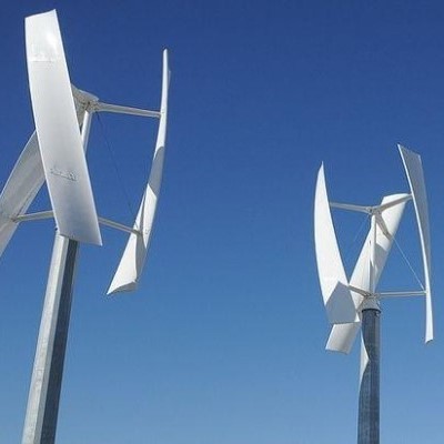 Wind turbines are machines that generate electricity from the kinetic energy of the wind. In history, they were more ...
Wind turbines are machines that generate electricity from the kinetic energy of the wind. In history, they were more ...Wind Turbine Glossary
 Wind energy is the kinetic energy that is present in moving air. The amount of potential energy depends mainly on wind speed, but ...
Wind energy is the kinetic energy that is present in moving air. The amount of potential energy depends mainly on wind speed, but ...Household Wind Energy System Components
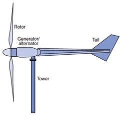 Basic parts of home wind energy systems generally comprise a rotor, a generator or alternator mounted on a frame, a tail ...
Basic parts of home wind energy systems generally comprise a rotor, a generator or alternator mounted on a frame, a tail ...Horizontal Axis Wind Turbine Design
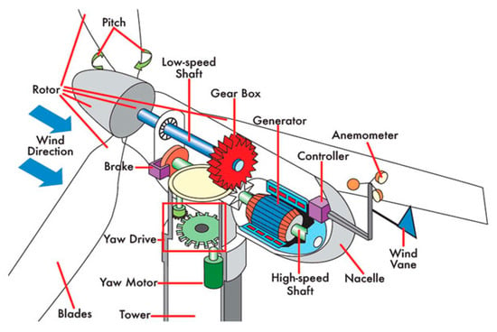
 Today, the most common design of wind turbine is the horizontal axis wind turbine (HAWT). That is, the axis of rotation is ...
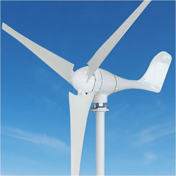
Today, the most common design of wind turbine is the horizontal axis wind turbine (HAWT). That is, the axis of rotation is ...What is a Wind Turbine?
 Wind turbines are devices that convert the kinetic energy from the wind into mechanical power, which can then be used to generate ...
Wind turbines are devices that convert the kinetic energy from the wind into mechanical power, which can then be used to generate ...