Home » Wind Turbine » Main Components of Wind Turbine
Main Components of Wind Turbine
To exploit the kinetic energy of the wind, by converting it into electrical energy available to be fed into the network or to supply loads in parallel, a wind turbine uses different components both mechanical as well as electrical. In particular, the rotor (blades and hub) extracts energy from the wind turning it into mechanical rotation energy and constitutes the “first motor” of the wind turbine, whereas conversion of mechanical energy into electrical energy is carried out by an electric generator according to suitable configurations.
This blog is going to give you a detailed overview of the main components of a wind turbine, if you are more interested in a cursory introduction, please click Wind Turbine Glossary.
To summarize, the main components constituting horizontal axis wind turbines are:

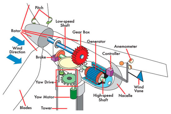
The converter and the transformer can be installed directly in the nacelle as Figure 1 shows, or positioned at the base of the tower. The installation of the transformer inside the nacelle allows balancing of the rotor weight, while positioning at the base allows a reduction in dimensions and weight of the nacelle.
In terms of costs, the percentage on the total cost of the different components is divided as shown in Figure 2.

Rotor
Blades
The blades are the components which interact with the wind and are designed with such an airfoil to maximize the aerodynamic efficiency. Figure 3 shows the typical form of a blade and its transversal sections; the blade winds up and the total angle between the root and the tip is about 25°.

Since the aerodynamic forces are proportional to the square of the relative speed, they increase rapidly with the distance from the hub; therefore it is important to design the part of the blade near the root so that there is a good lift and a low aerodynamic resistance.
Hub
The hub of the wind turbine is the component that connects the blades to the main shaft, transmitting to it the power extracted from the wind; it includes pitching systems.
Hubs are generally made of steel or spheroidal graphite iron and is protected externally by an oval enclosure called spinner. There are three main types of hub (Figure 4):

Figure 4
 Gearbox
Most drivetrains include a one- or more-stage gearbox between the rotor, which extracts kinetic energy from the wind and converts it into mechanical rotation energy, and the electric generator, which converts the available mechanical energy into electrical energy.
The gearbox has the purpose of increasing the rotor speed to adapt it to the values required by conventional generators (in some turbines the ratio of the gearbox may exceed 1:100). The gearbox consists of one or more gears of epicycloidal or parallel axis type.
Brakes
Nearly all wind turbines employ mechanical brakes mounted on the drivetrain, in addition to an aerodynamic brake. In many cases, mechanical brakes can stop the rotor under adverse weather conditions besides being used as “parking” brakes to keep the rotor from turning when the turbine is not operating.
There are two types of mechanical brakes in common usage:
Asynchronous Generator
It is essentially an induction three-phase motor characterized by a synchronous speed which depends on the number of poles and on the network frequency. If the mechanical torque acting on the rotor shaft is motive instead of resistant and makes the rotation speed increase and exceed the synchronous speed, the asynchronous machine stops working as a motor and starts working as a generator, thus putting electrical energy into the grid.
The relative difference between the synchronous speed and the effective rotation speed is called slip (s), which is negative when the machine is operated as a generator. In traditional asynchronous generators with squirrel cage rotor (short-circuit rotor), the slip is about 1% so that such devices are actually considered as having constant rotation speed.
The magnetizing current of the stator, which generates the rotating magnetic field in the air-gap, is supplied by the grid. Besides, such generator consumes a certain amount of reactive power, which shall be supplied by compensation systems, such as capacitors.
When a gust of wind hits a wind turbine equipped with a rotor asynchronous generator under short circuit, as the rotation speed is constant, there is a sudden variation of the torque and the consequent quick variation of the power output. If the short circuit power of the grid to which the wind turbine is connected is low, voltage fluctuations may occur on the electrical devices connected nearby and these fluctuations may cause malfunctioning of these devices. Moreover, it is possible to notice the quick variation of the luminous flux emitted by the lamps, generating that disturbing “fluttering” known as flicker. For this reason too, research has gone towards the development of variable speed systems which allow also the “torque pull” on the rotor to be reduced and the rotor to work at the point of maximum aerodynamic efficiency over a wide range of wind speed.
Variable speed solutions realized with induction generators are obtained by interposing a frequency converter between the stator of the generator with squirrel cage rotor and the grid, or by using a wound rotor asynchronous generator in which the rotor is supplied by an independent alternating current delivered by a frequency converter: thus, the synchronous speed results to be a function of the difference between the grid frequency and the frequency of the rotor current and it is possible to reach 30% speed variation.
Synchronous Generator
In this type of generator, also called alternator, the rotor consists of a direct current electromagnet or of permanent magnets. The frequency of the voltage induced on the stator (and consequently of the generated current) is directly proportional to the rotation speed of the rotor.
To allow functioning at variable speed, a frequency converter is interposed between alternator and grid; at first it transforms the current at variable frequency (as a function of the rotor speed and therefore of wind) coming out of the generator into direct current through an electronic rectifier, and then reconverts the direct current into alternating current at the network frequency through an inverter. Thus the frequency of the generated current is released from the grid frequency, which may also result into the abolition of the gearbox.
Thanks to the synchronous motor and to the frequency converter, when the wind strength suddenly increases, the rotor is let free to accelerate for some seconds: the increase in the rotation speed accumulates kinetic energy in the rotor itself and allows constant power supply. Vice versa, when the wind falls, the energy stored in the rotor is released while the rotor itself is slowing down.
Transformer
The electric power output from generators is usually in low voltage and shall be transformed into medium voltage through a transformer to reduce transmission losses by connection to the MV distribution network.
The transformer is installed on the nacelle or at the base of the tower. The electric cables connecting the nacelle to the base of the tower form a ring under the nacelle so that yaw movements are allowed. These movements are controlled and, in case of excessive rotation, the nacelle is yawned in the opposite direction to prevent cables from entangling. These cables must have such an increased length that the wind turbine shall be able to make up to three complete turns for alignment.
Yaw System
The nacelle is made to rotate on the top of the tower by an active yaw control system consisting of electrical actuators and relevant reduction gears (Figure 5), so that the rotor is always transversal to wind.

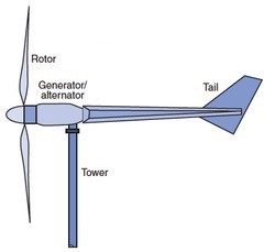
For horizontal axis turbines with downwind rotors, a yaw system is not necessary, since the turbine is intrinsically self-orienting and follows the wind direction as a wind vane. Instead, upwind turbines have either a rear orientation tail (small and medium size wind turbines) or active yaw control; therefore, the supporting tower shall be properly dimensioned also to withstand the torsional loads resulting from the use of yaw systems.
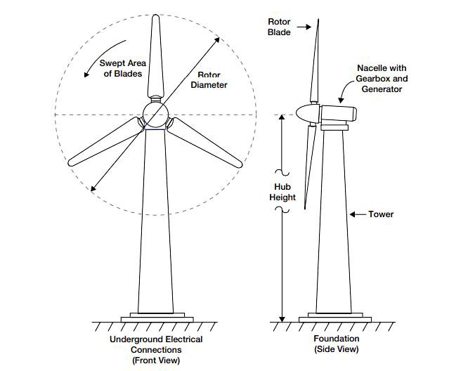
Tower
There are two main types of towers commonly used horizontal axis wind turbines (Figure 6):

The first wind turbines were on free-standing lattice towers, commonly used until the mid-1980s. Nowadays wind turbines are mostly of tubular type since they offer a number of advantages in comparison with the truss one. In particular, tubular towers do not require many bolted connections which need to be periodically checked; they provide a protected area to access the turbine and climbing to the nacelle is made safer and easier thanks to internal stairway or lift in case of larger turbines. Furthermore, they are aesthetically more acceptable in comparison with truss towers.
Control and Protection/Disconnection Systems
These systems are the “brain” of the wind turbine and provide the control logic to command start up and shut down procedures of the turbine and to guarantee turbine functioning in a defined range of operation parameters, by protecting the rotor, in particular, against overspeed, and the different parts of the electric circuit against overcurrents and overvoltages.
The logic of control is usually programmed in a PLC. In particular, the protection/disconnection systems disconnect the turbine from the grid in case of malfunctioning, thus allowing proper operation of the other wind turbines in the wind power plant.
Auxiliary Devices
The main auxiliary circuits mounted inside the nacelle comprise a hydraulic device to lubricate the gearbox or the other mechanical parts and also heat exchangers to cool the oil and the generator, pumps and fans included.
On the top of the nacelle there are anemometers and wanes for turbine control, aircraft warning lights and a possible platform for helicopters’ landing (for the access to offshore turbines). In order to improve the reliability of the wind turbine, different sensors are used to monitor the status of the various components and to signal any possible malfunctioning which needs maintenance operations. This is particularly true for offshore wind power plants, the access to which is not easy.
This blog is going to give you a detailed overview of the main components of a wind turbine, if you are more interested in a cursory introduction, please click Wind Turbine Glossary.
To summarize, the main components constituting horizontal axis wind turbines are:
- blade
- blade support
- pitch angle actuator
- hub
- spinner
- main support
- main shaft
- aircraft warning lights
- gearbox
- mechanical brakes
- hydraulic cooling devices
- generator
- power converter and electrical control, protection and disconnection devices
- anemometers
- transformer
- frame of the nacelle
- supporting tower
- yaw driving device
Figure 1
The converter and the transformer can be installed directly in the nacelle as Figure 1 shows, or positioned at the base of the tower. The installation of the transformer inside the nacelle allows balancing of the rotor weight, while positioning at the base allows a reduction in dimensions and weight of the nacelle.
In terms of costs, the percentage on the total cost of the different components is divided as shown in Figure 2.
Figure 2
Rotor
Blades
The blades are the components which interact with the wind and are designed with such an airfoil to maximize the aerodynamic efficiency. Figure 3 shows the typical form of a blade and its transversal sections; the blade winds up and the total angle between the root and the tip is about 25°.
Figure 3
Since the aerodynamic forces are proportional to the square of the relative speed, they increase rapidly with the distance from the hub; therefore it is important to design the part of the blade near the root so that there is a good lift and a low aerodynamic resistance.
Hub
The hub of the wind turbine is the component that connects the blades to the main shaft, transmitting to it the power extracted from the wind; it includes pitching systems.
Hubs are generally made of steel or spheroidal graphite iron and is protected externally by an oval enclosure called spinner. There are three main types of hub (Figure 4):
- rigid
- teetering
- hinged
Figure 4
GearboxMost drivetrains include a one- or more-stage gearbox between the rotor, which extracts kinetic energy from the wind and converts it into mechanical rotation energy, and the electric generator, which converts the available mechanical energy into electrical energy.
The gearbox has the purpose of increasing the rotor speed to adapt it to the values required by conventional generators (in some turbines the ratio of the gearbox may exceed 1:100). The gearbox consists of one or more gears of epicycloidal or parallel axis type.
Brakes
Nearly all wind turbines employ mechanical brakes mounted on the drivetrain, in addition to an aerodynamic brake. In many cases, mechanical brakes can stop the rotor under adverse weather conditions besides being used as “parking” brakes to keep the rotor from turning when the turbine is not operating.
There are two types of mechanical brakes in common usage:
- disc brakes
- clutch brakes
Asynchronous Generator
It is essentially an induction three-phase motor characterized by a synchronous speed which depends on the number of poles and on the network frequency. If the mechanical torque acting on the rotor shaft is motive instead of resistant and makes the rotation speed increase and exceed the synchronous speed, the asynchronous machine stops working as a motor and starts working as a generator, thus putting electrical energy into the grid.
The relative difference between the synchronous speed and the effective rotation speed is called slip (s), which is negative when the machine is operated as a generator. In traditional asynchronous generators with squirrel cage rotor (short-circuit rotor), the slip is about 1% so that such devices are actually considered as having constant rotation speed.
The magnetizing current of the stator, which generates the rotating magnetic field in the air-gap, is supplied by the grid. Besides, such generator consumes a certain amount of reactive power, which shall be supplied by compensation systems, such as capacitors.
When a gust of wind hits a wind turbine equipped with a rotor asynchronous generator under short circuit, as the rotation speed is constant, there is a sudden variation of the torque and the consequent quick variation of the power output. If the short circuit power of the grid to which the wind turbine is connected is low, voltage fluctuations may occur on the electrical devices connected nearby and these fluctuations may cause malfunctioning of these devices. Moreover, it is possible to notice the quick variation of the luminous flux emitted by the lamps, generating that disturbing “fluttering” known as flicker. For this reason too, research has gone towards the development of variable speed systems which allow also the “torque pull” on the rotor to be reduced and the rotor to work at the point of maximum aerodynamic efficiency over a wide range of wind speed.
Variable speed solutions realized with induction generators are obtained by interposing a frequency converter between the stator of the generator with squirrel cage rotor and the grid, or by using a wound rotor asynchronous generator in which the rotor is supplied by an independent alternating current delivered by a frequency converter: thus, the synchronous speed results to be a function of the difference between the grid frequency and the frequency of the rotor current and it is possible to reach 30% speed variation.
Synchronous Generator
In this type of generator, also called alternator, the rotor consists of a direct current electromagnet or of permanent magnets. The frequency of the voltage induced on the stator (and consequently of the generated current) is directly proportional to the rotation speed of the rotor.
To allow functioning at variable speed, a frequency converter is interposed between alternator and grid; at first it transforms the current at variable frequency (as a function of the rotor speed and therefore of wind) coming out of the generator into direct current through an electronic rectifier, and then reconverts the direct current into alternating current at the network frequency through an inverter. Thus the frequency of the generated current is released from the grid frequency, which may also result into the abolition of the gearbox.
Thanks to the synchronous motor and to the frequency converter, when the wind strength suddenly increases, the rotor is let free to accelerate for some seconds: the increase in the rotation speed accumulates kinetic energy in the rotor itself and allows constant power supply. Vice versa, when the wind falls, the energy stored in the rotor is released while the rotor itself is slowing down.
Transformer
The electric power output from generators is usually in low voltage and shall be transformed into medium voltage through a transformer to reduce transmission losses by connection to the MV distribution network.
The transformer is installed on the nacelle or at the base of the tower. The electric cables connecting the nacelle to the base of the tower form a ring under the nacelle so that yaw movements are allowed. These movements are controlled and, in case of excessive rotation, the nacelle is yawned in the opposite direction to prevent cables from entangling. These cables must have such an increased length that the wind turbine shall be able to make up to three complete turns for alignment.
Yaw System
The nacelle is made to rotate on the top of the tower by an active yaw control system consisting of electrical actuators and relevant reduction gears (Figure 5), so that the rotor is always transversal to wind.
Figure 5
The direction and speed of the wind are continuously controlled by the sensors connected on the roof of the nacelle. The rotor is generally positioned according to the average direction of the wind, calculated over a 10min period by the turbine control system.For horizontal axis turbines with downwind rotors, a yaw system is not necessary, since the turbine is intrinsically self-orienting and follows the wind direction as a wind vane. Instead, upwind turbines have either a rear orientation tail (small and medium size wind turbines) or active yaw control; therefore, the supporting tower shall be properly dimensioned also to withstand the torsional loads resulting from the use of yaw systems.
Tower
There are two main types of towers commonly used horizontal axis wind turbines (Figure 6):
- free-standing lattice (truss)
- tubular
Figure 6
The first wind turbines were on free-standing lattice towers, commonly used until the mid-1980s. Nowadays wind turbines are mostly of tubular type since they offer a number of advantages in comparison with the truss one. In particular, tubular towers do not require many bolted connections which need to be periodically checked; they provide a protected area to access the turbine and climbing to the nacelle is made safer and easier thanks to internal stairway or lift in case of larger turbines. Furthermore, they are aesthetically more acceptable in comparison with truss towers.
Control and Protection/Disconnection Systems
These systems are the “brain” of the wind turbine and provide the control logic to command start up and shut down procedures of the turbine and to guarantee turbine functioning in a defined range of operation parameters, by protecting the rotor, in particular, against overspeed, and the different parts of the electric circuit against overcurrents and overvoltages.
The logic of control is usually programmed in a PLC. In particular, the protection/disconnection systems disconnect the turbine from the grid in case of malfunctioning, thus allowing proper operation of the other wind turbines in the wind power plant.
Auxiliary Devices
The main auxiliary circuits mounted inside the nacelle comprise a hydraulic device to lubricate the gearbox or the other mechanical parts and also heat exchangers to cool the oil and the generator, pumps and fans included.
On the top of the nacelle there are anemometers and wanes for turbine control, aircraft warning lights and a possible platform for helicopters’ landing (for the access to offshore turbines). In order to improve the reliability of the wind turbine, different sensors are used to monitor the status of the various components and to signal any possible malfunctioning which needs maintenance operations. This is particularly true for offshore wind power plants, the access to which is not easy.
Post a Comment:
You may also like:

Featured Articles
Horizontal Axis Wind Turbine Design
 Today, the most common design of wind turbine is the horizontal axis wind turbine (HAWT). That is, the axis of rotation is ...
Today, the most common design of wind turbine is the horizontal axis wind turbine (HAWT). That is, the axis of rotation is ...Overvoltage Protection for Wind ...
 Due to their principle of operation, wind turbines have to be set up outdoors and are used in a wide range of ...
Due to their principle of operation, wind turbines have to be set up outdoors and are used in a wide range of ...What is a Wind Turbine?
 Wind turbines are devices that convert the kinetic energy from the wind into mechanical power, which can then be used to generate ...
Wind turbines are devices that convert the kinetic energy from the wind into mechanical power, which can then be used to generate ...Household Wind Energy System Components
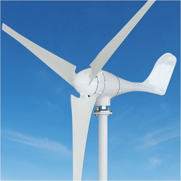
 Basic parts of home wind energy systems generally comprise a rotor, a generator or alternator mounted on a frame, a tail ...
Basic parts of home wind energy systems generally comprise a rotor, a generator or alternator mounted on a frame, a tail ...Wind Turbine Glossary
 Wind energy is the kinetic energy that is present in moving air. The amount of potential energy depends mainly on wind speed, but ...
Wind energy is the kinetic energy that is present in moving air. The amount of potential energy depends mainly on wind speed, but ...